After Hours Shipping

Real Time Order Tracking

Flexible Delivery Options

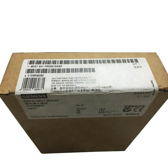
| Article number | 6ES7321-7RD00-0AB0 |
| SM321, 4DI, DC24V, HAZARDOUS AREAS | |
| Supply voltage | |
| Load voltage L+ | |
|
● Rated value (DC)
|
24 V |
|
● Reverse polarity protection
|
Yes |
| Input current | |
| from load voltage L+ (without load), max. | 50 mA |
| from backplane bus 5 V DC, max. | 80 mA |
| Encoder supply | |
| Type of output voltage | via the inputs |
| Power loss | |
| Power loss, typ. | 1.1 W |
| Digital inputs | |
| Number of digital inputs | 4 |
| Number of NAMUR inputs | 4 |
| Input voltage | |
|
● Type of input voltage
|
DC |
|
● Rated value (DC)
|
8.2 V; from internal power circuit supply |
| Input current | |
|
● on wire-break, max.
|
0.1 mA |
|
● on short-circuit, max.
|
8.5 mA |
| for NAMUR encoders | |
|
— for signal “0”
|
0.35 to 1.2 mA |
|
— for signal “1”
|
2.1 to 7 mA |
| Input delay (for rated value of input voltage) | |
|
● Input frequency (with a time delay of 0.1 ms), max.
|
2 kHz |
| for NAMUR inputs | |
|
— parameterizable
|
Yes; 0.1 / 0.5 / 3 / 15 / 20 ms (plus 0.25 ms preparation time) |
| Cable length | |
|
● unshielded, max.
|
200 m |
| Encoder | |
| Connectable encoders | |
|
● NAMUR encoder
|
Yes; Two-wire connection |
| Interrupts/diagnostics/status information | |
| Diagnostics function | Yes |
| Diagnoses | |
|
● Diagnostic information readable
|
Yes |
| Diagnostics indication LED | |
|
● Group error SF (red)
|
Yes |
|
● Status indicator digital input (green)
|
Yes |
|
● Channel fault indicator F (red)
|
Yes |
| Ex(i) characteristics | |
| Module for Ex(i) protection | Yes |
| Maximum values of input circuits (per channel) | |
|
● Co (permissible external capacity), max.
|
3 µF |
|
● Io (short-circuit current), max.
|
14.1 mA |
|
● Lo (permissible external inductivity), max.
|
100 mH |
|
● Po (power of load), max.
|
33.7 mW |
|
● Uo (output no-load voltage), max.
|
10 V |
| Potential separation | |
| Potential separation digital inputs | |
|
● between the channels
|
Yes; 60 V DC/30 V AC when used in the hazardous area; 400 V DC/250 V AC when used in NON-hazardous area |
|
● between the channels, in groups of
|
1 |
|
● between the channels and backplane bus
|
Yes; 60 V DC/30 V AC when used in the hazardous area; 400 V DC/250 V AC when used in NON-hazardous area |
|
● Between the channels and load voltage L+
|
Yes; 60 V DC/30 V AC when used in the hazardous area; 400 V DC/250 V AC when used in NON-hazardous area |
| Standards, approvals, certificates | |
| Use in hazardous areas | |
|
● Type of protection acc. to EN 50020 (CENELEC)
|
[EEx ib] IIC |
|
● Type of protection acc. to FM
|
Class II, Division 2, Group A, B, C, D T4 |
|
● Test number PTB
|
Ex-96.D.2094X |
| Ambient conditions | |
| Ambient temperature during operation | |
|
● max.
|
60 °C |
| Connection method | |
| required front connector | 20-pin |
| Dimensions | |
| Width | 40 mm |
| Height | 125 mm |
| Depth | 120 mm |
| Weights | |
| Weight, approx. | 230 g |