After Hours Shipping

Real Time Order Tracking

Flexible Delivery Options

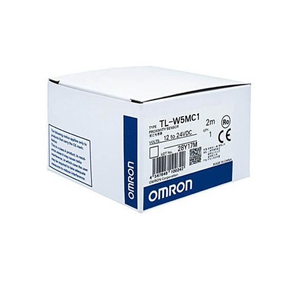
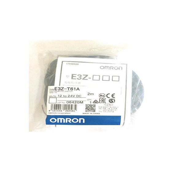
| Model
Item |
E2S-W11 E2S-W12 | E2S-Q11 E2S-Q12 | E2S-W21 E2S-W22 | E2S-Q21 E2S-Q22 |
| Sensing surface | Top | Front | Top | Front |
| Sensing distance | 1.6 mm ±15% | 2.5 mm ±15% | ||
| Set distance | 0 to 1.2 mm | 0 to 1.9 mm | ||
| Differential travel | 10% max. of sensing distance | |||
| Detectable object | Ferrous metal (The sensing distance decreases with non-ferrous metal. Refer to Engineering Data on page 4.) | |||
| Standard sensing object | Iron, 12 ´ 12 ´ 1 mm | Iron, 15 ´ 15 ´ 1 mm | ||
| Response frequency * | 1 kHz min. | |||
| Power supply voltage (operating voltage range) |
12 to 24 VDC (10 to 30 VDC), ripple (p-p): 10% max. |
|||
| Leakage current | 0.8 mA max. | |||
| Load current | 3 to 50 mA max. | |||
| Residual voltage | 3 V max. (under load current of 50 mA with cable length of 1 m) | |||
| Indicators | @@1 Models: Operation indicator (red), Setting indicator (green)
@@2 Models: Operation indicator (red) |
|||
| Operation mode (with sensing object approaching) | @@1 Models: NO
@@2 Models: NC Refer to the timing charts under I/O Circuit Diagrams on page 5 for details. |
|||