After Hours Shipping

Real Time Order Tracking

Flexible Delivery Options

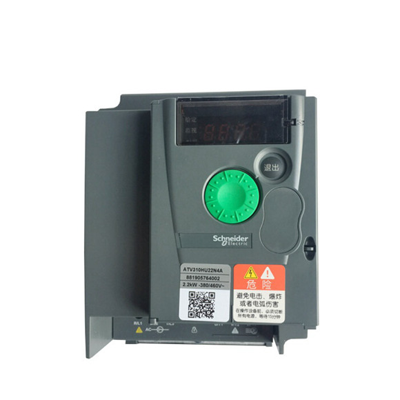
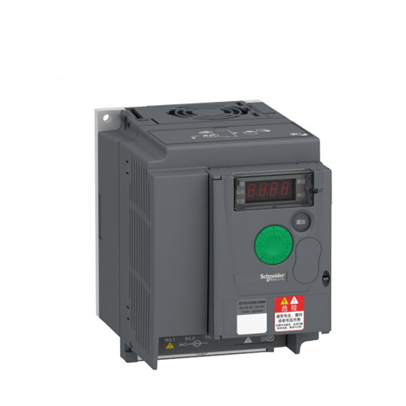
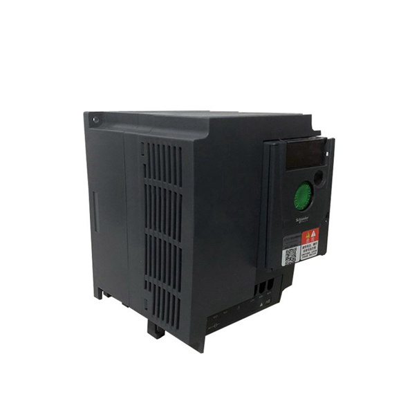
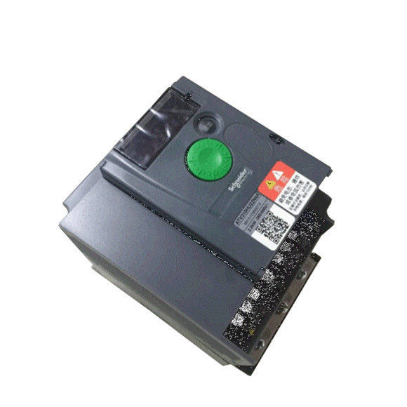
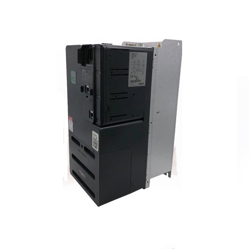
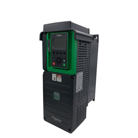
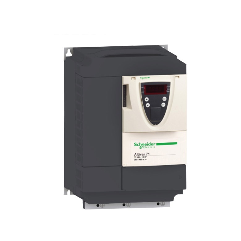
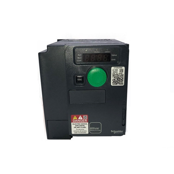
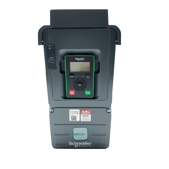
| Item | Schneider VFD Inverter Drive ATV31 0.37kW-11kW | |
| range of product | Altivar 31 | |
| product or component type | Variable speed drive | |
| product destination | Asynchronous motors | |
| product specific application | Simple machine Wire guiding |
|
| assembly style | Enclosed | |
| component name | ATV31 | |
| EMC filter | Integrated | |
| power supply voltage | 380…500 V – 15…10 % | |
| power supply frequency | 50…60 Hz – 5…5 % | |
| network number of phases | 3 phases | |
| motor power kW | 5.5 kW | |
| motor power hp | 7.5 hp | |
| line current | 16.5 A 500 V 1 kA 21.9 A 380 V 1 kA |
|
| apparent power | 15 kVA | |
| maximum prospective line Isc | 22 kA | |
| nominal output current | 14.3 A 4 kHz | |
| maximum transient current | 21.5 A for 60 s | |
| power dissipation in W | 232 W at nominal load | |
| speed range | 1…50 | |
| transient overtorque | 150…170 % of nominal motor torque | |
| asynchronous motor control profile | Sensorless flux vector control with PWM type motor control signal Factory set : constant torque |
|
| analogue input number | 3 | |
| IP degree of protection | IP55 | |
| power supply voltage limit | 323…550 V | |
| power supply frequency limits | 47.5…63 Hz | |
| speed drive output frequency | 0.5…500 Hz | |
| nominal switching frequency | 4 kHz | |
| switching frequency | 2…16 kHz adjustable | |
| braking torque | <= 150 % during 60 s with braking resistor 100 % with braking resistor continuously 30 % without braking resistor |
|
| regulation loop | Frequency PI regulator | |
| motor slip compensation | Adjustable Automatic whatever the load Suppressable |
|
| output voltage | <= power supply voltage | |
| electrical connection | Al1, Al2, Al3, AOV, AOC, R1A, R1B, R1C, R2A, R2B, LI1…LI6 terminal 2.5 mm² AWG 14 L1, L2, L3, U, V, W, PA, PB, PA/+, PC/- terminal 2.5 mm² AWG 14 |
|
| tightening torque | Al1, Al2, Al3, AOV, AOC, R1A, R1B, R1C, R2A, R2B, LI1…LI6: 0.6 N.m L1, L2, L3, U, V, W, PA, PB, PA/+, PC/-: 0.8 N.m |
|
| insulation | Electrical between power and control | |
| supply | Internal supply for logic inputs 19…30 V, <100 mA overload protection Internal supply for logic inputs 19…30 V, <100 mA short-circuit protection Internal supply for reference potentiometer 10…10.8 V, <10 mA overload protection Internal supply for reference potentiometer 10…10.8 V, <10 mA short-circuit protection |
|
| analogue input type | AI3 configurable current 0…20 mA, impedance: 250 Ohm AI1 configurable voltage 0…10 V, input voltage 30 V max, impedance: 30000 Ohm AI2 configurable voltage +/- 10 V, input voltage 30 V max, impedance: 30000 Ohm |
|
| input sampling time | LI1…LI6: 4 ms discrete AI1, AI2, AI3: 8 ms analog |
|
| output response time | AOV, AOC 8 ms for analog R1A, R1B, R1C, R2A, R2B 8 ms for discrete |
|
| linearity error | +/- 0.2 % for output | |
| analogue output number | 2 | |
| analogue output type | AOC configurable current: 0…20 mA, impedance: 800 Ohm, resolution: 8 bits AOV configurable voltage: 0…10 V, impedance: 470 Ohm, resolution: 8 bits |
|
| discrete input logic | Positive logic (source) (LI1…LI6), < 5 V (state 0), > 11 V (state 1) Logic input not wired (LI1…LI4), < 13 V (state 1) Negative logic (source) (LI1…LI6), > 19 V (state 0) |
|
| discrete output number | 2 | |
| discrete output type | Configurable relay logic: (R1A, R1B, R1C) 1 NO + 1 NC – 100000 cycles Configurable relay logic: (R2A, R2B) NC – 100000 cycles |
|
| minimum switching current | 10 mA 5 V DC R1-R2 | |
| maximum switching current | 2 A at 250 V AC on inductive load – cos phi = 0.4 – L/R = 7 ms (R1-R2) 2 A at 30 V DC on inductive load – cos phi = 0.4 – L/R = 7 ms (R1-R2) 5 A at 250 V AC on resistive load – cos phi = 1 – L/R = 0 ms (R1-R2) 5 A at 30 V DC on resistive load – cos phi = 1 – L/R = 0 ms (R1-R2) |
|
| discrete input number | 6 | |
| discrete input type | (LI1…LI6) programmable at 24 V, 0…100 mA for PLC, impedance: 3500 Ohm | |
| acceleration and deceleration ramps | S, U or customized Linear adjustable separately from 0.1 to 999.9 s |
|
| braking to standstill | By DC injection | |
| protection type | Input phase breaks: drive Line supply overvoltage and undervoltage safety circuits: drive Line supply phase loss safety function, for three phases supply: drive Motor phase breaks: drive Overcurrent between output phases and earth (on power up only): drive Overheating protection: drive Short-circuit between motor phases: drive Thermal protection: motor |
|
| insulation resistance | >= 500 mOhm 500 V DC for 1 minute | |
| local signalling | 1 LED (red)drive voltage: Four 7-segment display unitsCANopen bus status: |
|
| time constant | 5 ms for reference change | |
| frequency resolution | Display unit: 0.1 Hz Analog input: 0.1…100 Hz |
|
| communication port protocol | Modbus CANopen |
|
| connector type | 1 RJ45 for CANopen via VW3 CANTAP2 adaptor 1 RJ45 for Modbus |
|
| physical interface | RS485 multidrop serial link for Modbus | |
| transmission frame | RTU for Modbus | |
| transmission rate | 10, 20, 50, 125, 250, 500 kbps or 1 Mbps for CANopen via VW3 CANTAP2 adaptor 4800, 9600 or 19200 bps for Modbus |
|
| number of addresses | 1…127 for CANopen via VW3 CANTAP2 adaptor 1…247 for Modbus |
|
| number of drive | 127 for CANopen via VW3 CANTAP2 adaptor 31 for Modbus |
|
| marking | CE | |
| operating position | Vertical +/- 10 degree | |
| net weight | 23.6 kg | |