| Article number |
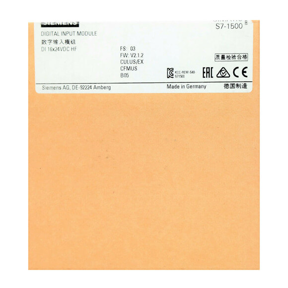
6ES7521-1BH00-0AB0 |
6ES7521-1BL00-0AB0 |
6ES7521-1BH50-0AA0 |
6ES7521-1FH00-0AA0 |
6ES7521-7EH00-0AB0 |
|
S7-1500, DI 16x24VDC HF |
S7-1500, DI 32x24VDC HF |
S7-1500, DI 16x24VDC SRC BA |
S7-1500, DI 16x230VAC BA |
S7-1500, DI 16 x 24…125V UC HF |
| General information |
|
|
|
|
|
| Product type designation |
DI 16x24VDC HF |
DI 32x24VDC HF |
DI 16x24VDC SRC BA |
DI 16x230VAC BA |
DI 16×24 … 125 V UC HF |
| HW functional status |
from FS04 |
from FS04 |
FS01 |
FS01 |
FS01 |
| Firmware version |
V2.2.0 |
V2.2.1 |
V2.0.0 |
V2.0.0 |
V1.0.0 |
| ● FW update possible |
Yes |
Yes |
Yes |
Yes |
Yes |
| Product function |
|
|
|
|
|
| ● I&M data |
Yes; I&M0 to I&M3 |
Yes; I&M0 to I&M3 |
Yes; I&M0 to I&M3 |
Yes; I&M0 to I&M3 |
Yes; I&M0 to I&M3 |
| ● Isochronous mode |
Yes |
Yes |
No |
No |
No |
| ● Prioritized startup |
Yes |
Yes |
Yes |
Yes |
Yes |
| Engineering with |
|
|
|
|
|
| ● STEP 7 TIA Portal configurable/integrated from version |
V13 SP1 / – |
V13 SP1 / – |
V12 / V12 |
V12 / V12 |
V13 SP1 / – |
| ● STEP 7 configurable/integrated from version |
V5.5 SP3 / – |
V5.5 SP3 / – |
V5.5 SP3 / – |
V5.5 SP3 / – |
V5.5 SP3 / – |
| ● PROFIBUS from GSD version/GSD revision |
V1.0 / V5.1 |
V1.0 / V5.1 |
V1.0 / V5.1 |
V1.0 / V5.1 |
V1.0 / V5.1 |
| ● PROFINET from GSD version/GSD revision |
V2.3 / – |
V2.3 / – |
V2.3 / – |
V2.3 / – |
V2.3 / – |
| Operating mode |
|
|
|
|
|
| ● DI |
Yes |
Yes |
Yes |
Yes |
Yes |
| ● Counter |
Yes |
Yes |
No |
No |
No |
| ● Oversampling |
No |
No |
|
|
No |
| ● MSI |
Yes |
Yes |
Yes |
Yes |
Yes |
| Supply voltage |
|
|
|
|
|
| Rated value (DC) |
24 V |
24 V |
|
|
|
| permissible range, lower limit (DC) |
20.4 V |
20.4 V |
20.4 V |
|
|
| permissible range, upper limit (DC) |
28.8 V |
28.8 V |
28.8 V |
|
|
| Reverse polarity protection |
Yes |
Yes |
|
|
|
| Input current |
|
|
|
|
|
| Current consumption, max. |
20 mA; with 24 V DC supply |
40 mA; 20 mA per group with 24 V DC supply |
|
|
|
| Power |
|
|
|
|
|
| Power available from the backplane bus |
1.1 W |
1.1 W |
0.9 W |
1 W |
1.2 W |
| Power loss |
|
|
|
|
|
| Power loss, typ. |
2.6 W |
4.2 W |
2.8 W |
4.9 W |
2.2 W; At 24 V DC; 6.0 W at 125 V AC |
| Digital inputs |
|
|
|
|
|
| Number of digital inputs |
16 |
32 |
16 |
16 |
16 |
| Digital inputs, parameterizable |
Yes |
Yes |
No |
No |
Yes |
| Source/sink input |
P-reading |
P-reading |
Sourcing |
P-reading |
Yes |
| Input characteristic curve in accordance with IEC 61131, type 1 |
|
|
|
Yes |
|
| Input characteristic curve in accordance with IEC 61131, type 3 |
Yes |
Yes |
Yes |
|
Yes; At 24 V DC |
| Digital input functions, parameterizable |
|
|
|
|
|
| ● Gate start/stop |
Yes |
Yes |
|
|
|
| ● Freely usable digital input |
Yes |
Yes |
|
|
|
| ● Counter |
|
|
|
|
|
| — Number, max. |
2 |
2 |
|
|
|
| — Counting frequency, max. |
3 kHz |
3 kHz; FS04 and FW V2.2.1 or higher |
|
|
|
| — Counting width |
32 bit |
32 bit |
|
|
|
| — Counting direction up/down |
Up |
Up |
|
|
|
| Input voltage |
|
|
|
|
|
| ● Rated value (DC) |
24 V |
24 V |
24 V |
|
24 V; 48 V, 125 V |
| — 24 V DC |
Yes |
Yes |
Yes |
|
Yes |
| ● Rated value (AC) |
|
|
|
230 V; 120/230 V AC, 50/60 Hz |
24 V; 48 V, 125 V (50 – 60 Hz) |
| ● for signal “0” |
-30 to +5 V |
-30 to +5 V |
-5 to +30V |
0V AC to 40V AC |
-5 … +5 V |
| ● for signal “1” |
+11 to +30V |
+11 to +30V |
-11 to -30V |
79V AC to 264V AC |
+11 … +146 V |
| Input current |
|
|
|
|
|
| ● for signal “1”, typ. |
2.5 mA |
2.5 mA |
4.5 mA |
11 mA; At 230 V AC and 5.5 mA at 120 V AC |
3 mA; At 24 V DC |
| Input delay (for rated value of input voltage) |
|
|
|
|
|
| for standard inputs |
|
|
|
|
|
| — parameterizable |
Yes; 0.05 / 0.1 / 0.4 / 1.6 / 3.2 / 12.8 / 20 ms |
Yes; 0.05 / 0.1 / 0.4 / 1.6 / 3.2 / 12.8 / 20 ms |
No |
No |
Yes; 0.05 / 0.1 / 0.4 / 1.6 / 3.2 / 12.8 / 20 ms parameterizable with DC, 20 ms fixed with AC |
| — at “0” to “1”, min. |
0.05 ms |
0.05 ms |
3 ms |
|
0.05 ms |
| — at “0” to “1”, max. |
20 ms |
20 ms |
4 ms |
25 ms |
20 ms |
| — at “1” to “0”, min. |
0.05 ms |
0.05 ms |
3 ms |
|
0.05 ms |
| — at “1” to “0”, max. |
20 ms |
20 ms |
4 ms |
25 ms |
20 ms |
| for interrupt inputs |
|
|
|
|
|
| — parameterizable |
Yes |
Yes |
No |
No |
Yes |
| for technological functions |
|
|
|
|
|
| — parameterizable |
Yes |
Yes |
No |
No |
No |
| Cable length |
|
|
|
|
|
| ● shielded, max. |
1 000 m |
1 000 m |
1 000 m |
1 000 m |
1 000 m |
| ● unshielded, max. |
600 m |
600 m |
600 m |
600 m |
600 m |
| Encoder |
|
|
|
|
|
| Connectable encoders |
|
|
|
|
|
| ● 2-wire sensor |
Yes |
Yes |
Yes |
Yes |
Yes |
| — permissible quiescent current (2-wire sensor), max. |
1.5 mA |
1.5 mA |
1.5 mA |
2 mA |
1.5 mA |
| Isochronous mode |
|
|
|
|
|
| Filtering and processing time (TCI), min. |
80 µs; At 50 μs filter time |
80 µs; At 50 μs filter time |
|
|
|
| Bus cycle time (TDP), min. |
250 µs |
250 µs |
|
|
|
| Interrupts/diagnostics/status information |
|
|
|
|
|
| Diagnostics function |
Yes |
Yes |
No |
No |
Yes |
| Alarms |
|
|
|
|
|
| ● Diagnostic alarm |
Yes |
Yes |
No |
No |
Yes |
| ● Hardware interrupt |
Yes |
Yes |
No |
No |
Yes |
| Diagnoses |
|
|
|
|
|
| ● Monitoring the supply voltage |
Yes |
Yes |
No |
No |
No |
| ● Wire-break |
Yes; to I < 350 µA |
Yes; to I < 350 µA |
No |
No |
Yes; To I < 550 µA |
| ● Short-circuit |
No |
No |
No |
No |
No |
| Diagnostics indication LED |
|
|
|
|
|
| ● RUN LED |
Yes; green LED |
Yes; green LED |
Yes; green LED |
Yes; green LED |
Yes; green LED |
| ● ERROR LED |
Yes; red LED |
Yes; red LED |
Yes; red LED |
Yes; red LED |
Yes; red LED |
| ● Monitoring of the supply voltage (PWR-LED) |
Yes; green LED |
Yes; green LED |
No |
No |
No |
| ● Channel status display |
Yes; green LED |
Yes; green LED |
Yes; green LED |
Yes; green LED |
Yes; green LED |
| ● for channel diagnostics |
Yes; red LED |
Yes; red LED |
No |
No |
Yes; red LED |
| ● for module diagnostics |
Yes; red LED |
Yes; red LED |
No |
Yes; red LED |
Yes; red LED |
| Potential separation |
|
|
|
|
|
| Potential separation channels |
|
|
|
|
|
| ● between the channels |
No |
Yes |
No |
No |
Yes |
| ● between the channels, in groups of |
16 |
16 |
16 |
4 |
1 |
| ● between the channels and backplane bus |
Yes |
Yes |
Yes |
Yes |
Yes |
| ● between the channels and the power supply of the electronics |
No |
No |
|
|
|
| Permissible potential difference |
|
|
|
|
|
| between different circuits |
|
|
|
250 V AC between the channels and the backplane bus; 500 V AC between the channels |
146 V DC/132 V AC |
| Isolation |
|
|
|
|
|
| Isolation tested with |
707 V DC (type test) |
707 V DC (type test) |
707 V DC (type test) |
3 100 V DC |
2 000 V DC |
| Standards, approvals, certificates |
|
|
|
|
|
| Suitable for safety functions |
No |
No |
No |
No |
No |
| Ambient conditions |
|
|
|
|
|
| Ambient temperature during operation |
|
|
|
|
|
| ● horizontal installation, min. |
-30 °C; From FS05 |
-30 °C; From FS05 |
0 °C |
0 °C |
0 °C |
| ● horizontal installation, max. |
60 °C |
60 °C |
60 °C |
60 °C |
60 °C |
| ● vertical installation, min. |
-30 °C; From FS05 |
-30 °C; From FS05 |
0 °C |
0 °C |
0 °C |
| ● vertical installation, max. |
40 °C |
40 °C |
40 °C |
40 °C |
40 °C |
| Altitude during operation relating to sea level |
|
|
|
|
|
| ● Installation altitude above sea level, max. |
5 000 m; Restrictions for installation altitudes > 2 000 m, see manual |
5 000 m; Restrictions for installation altitudes > 2 000 m, see manual |
5 000 m; Restrictions for installation altitudes > 2 000 m, see manual |
|
|
| Dimensions |
|
|
|
|
|
| Width |
35 mm |
35 mm |
35 mm |
35 mm |
35 mm |
| Height |
147 mm |
147 mm |
147 mm |
147 mm |
147 mm |
| Depth |
129 mm |
129 mm |
129 mm |
129 mm |
129 mm |
| Weights |
|
|
|
|
|
| Weight, approx. |
240 g |
260 g |
230 g |
300 g |
240 g |