After Hours Shipping

Real Time Order Tracking

Flexible Delivery Options

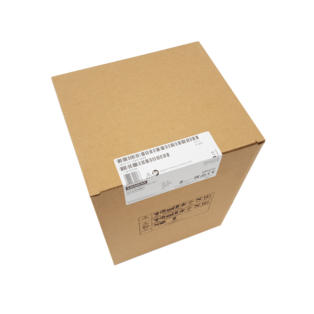
| Article number | 6ES7515-2FM02-0AB0 |
| CPU 1515F-2 PN, 750KB Prog.,3MB Data | |
| General information | |
| Product type designation | CPU 1515F-2 PN |
| HW functional status | FS01 |
| Firmware version | V2.8 |
| Product function | |
|
● I&M data
|
Yes; I&M0 to I&M3 |
|
● Isochronous mode
|
Yes; Distributed and central; with minimum OB 6x cycle of 500 µs (distributed) and 1 ms (central) |
| Engineering with | |
|
● STEP 7 TIA Portal configurable/integrated from version
|
V16 (FW V2.8) / as of V13 SP1 (FW V1.8) configurable with 6ES7515-2FM01-0AB0 |
| Configuration control | |
| via dataset | Yes |
| Display | |
| Screen diagonal [cm] | 6.1 cm |
| Control elements | |
| Number of keys | 8 |
| Mode buttons | 2 |
| Supply voltage | |
| Type of supply voltage | 24 V DC |
| permissible range, lower limit (DC) | 19.2 V |
| permissible range, upper limit (DC) | 28.8 V |
| Reverse polarity protection | Yes |
| Mains buffering | |
|
● Mains/voltage failure stored energy time
|
5 ms |
|
● Repeat rate, min.
|
1/s |
| Input current | |
| Current consumption (rated value) | 0.8 A |
| Current consumption, max. | 1.1 A |
| Inrush current, max. | 2.4 A; Rated value |
| I²t | 0.02 A²·s |
| Power | |
| Infeed power to the backplane bus | 12 W |
| Power consumption from the backplane bus (balanced) | 6.2 W |
| Power loss | |
| Power loss, typ. | 6.3 W |
| Memory | |
| Number of slots for SIMATIC memory card | 1 |
| SIMATIC memory card required | Yes |
| Work memory | |
|
● integrated (for program)
|
750 kbyte |
|
● integrated (for data)
|
3 Mbyte |
| Load memory | |
|
● Plug-in (SIMATIC Memory Card), max.
|
32 Gbyte |
| Backup | |
|
● maintenance-free
|
Yes |
| CPU processing times | |
| for bit operations, typ. | 30 ns |
| for word operations, typ. | 36 ns |
| for fixed point arithmetic, typ. | 48 ns |
| for floating point arithmetic, typ. | 192 ns |
| CPU-blocks | |
| Number of elements (total) | 6 000; Blocks (OB, FB, FC, DB) and UDTs |
| DB | |
|
● Number range
|
1 … 60 999; subdivided into: number range that can be used by the user: 1 … 59 999, and number range of DBs created via SFC 86: 60 000 … 60 999 |
|
● Size, max.
|
3 Mbyte; For DBs with absolute addressing, the max. size is 64 KB |
| FB | |
|
● Number range
|
0 … 65 535 |
|
● Size, max.
|
500 kbyte |
| FC | |
|
● Number range
|
0 … 65 535 |
|
● Size, max.
|
500 kbyte |
| OB | |
|
● Size, max.
|
500 kbyte |
|
● Number of free cycle OBs
|
100 |
|
● Number of time alarm OBs
|
20 |
|
● Number of delay alarm OBs
|
20 |
|
● Number of cyclic interrupt OBs
|
20; With minimum OB 3x cycle of 500 µs |
|
● Number of process alarm OBs
|
50 |
|
● Number of DPV1 alarm OBs
|
3 |
|
● Number of isochronous mode OBs
|
2 |
|
● Number of technology synchronous alarm OBs
|
2 |
|
● Number of startup OBs
|
100 |
|
● Number of asynchronous error OBs
|
4 |
|
● Number of synchronous error OBs
|
2 |
|
● Number of diagnostic alarm OBs
|
1 |
| Nesting depth | |
|
● per priority class
|
24; Up to 8 possible for F-blocks |
| Counters, timers and their retentivity | |
| S7 counter | |
|
● Number
|
2 048 |
| Retentivity | |
|
— adjustable
|
Yes |
| IEC counter | |
|
● Number
|
Any (only limited by the main memory) |
| Retentivity | |
|
— adjustable
|
Yes |
| S7 times | |
|
● Number
|
2 048 |
| Retentivity | |
|
— adjustable
|
Yes |
| IEC timer | |
|
● Number
|
Any (only limited by the main memory) |
| Retentivity | |
|
— adjustable
|
Yes |
| Data areas and their retentivity | |
| Retentive data area (incl. timers, counters, flags), max. | 512 kbyte; In total; available retentive memory for bit memories, timers, counters, DBs, and technology data (axes): 472 KB |
| Extended retentive data area (incl. timers, counters, flags), max. | 3 Mbyte; When using PS 6 0W 24/48/60 V DC HF |
| Flag | |
|
● Number, max.
|
16 kbyte |
|
● Number of clock memories
|
8; 8 clock memory bit, grouped into one clock memory byte |
| Data blocks | |
|
● Retentivity adjustable
|
Yes |
|
● Retentivity preset
|
No |
| Local data | |
|
● per priority class, max.
|
64 kbyte; max. 16 KB per block |
| Address area | |
| Number of IO modules | 8 192; max. number of modules / submodules |
| I/O address area | |
|
● Inputs
|
32 kbyte; All inputs are in the process image |
|
● Outputs
|
32 kbyte; All outputs are in the process image |
| per integrated IO subsystem | |
|
— Inputs (volume)
|
8 kbyte |
|
— Outputs (volume)
|
8 kbyte |
| per CM/CP | |
|
— Inputs (volume)
|
8 kbyte |
|
— Outputs (volume)
|
8 kbyte |
| Subprocess images | |
|
● Number of subprocess images, max.
|
32 |
| Hardware configuration | |
| Number of distributed IO systems | 64; A distributed I/O system is characterized not only by the integration of distributed I/O via PROFINET or PROFIBUS communication modules, but also by the connection of I/O via AS-i master modules or links (e.g. IE/PB-Link) |
| Number of DP masters | |
|
● Via CM
|
8; A maximum of 8 CMs/CPs (PROFIBUS, PROFINET, Ethernet) can be inserted in total |
| Number of IO Controllers | |
|
● integrated
|
2 |
|
● Via CM
|
8; A maximum of 8 CMs/CPs (PROFIBUS, PROFINET, Ethernet) can be inserted in total |
| Rack | |
|
● Modules per rack, max.
|
32; CPU + 31 modules |
|
● Number of lines, max.
|
1 |
| PtP CM | |
|
● Number of PtP CMs
|
the number of connectable PtP CMs is only limited by the number of available slots |
| Time of day | |
| Clock | |
|
● Type
|
Hardware clock |
|
● Backup time
|
6 wk; At 40 °C ambient temperature, typically |
|
● Deviation per day, max.
|
10 s; Typ.: 2 s |