After Hours Shipping

Real Time Order Tracking

Flexible Delivery Options

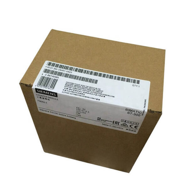
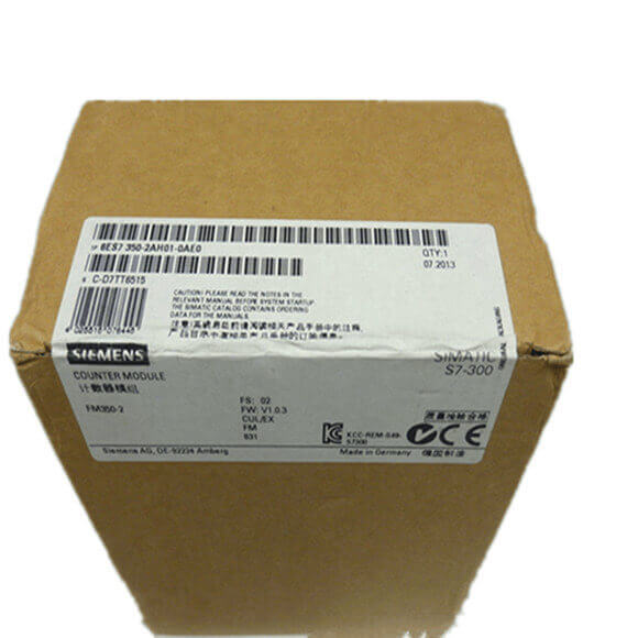
| Article number | 6ES7350-2AH01-0AE0 |
| FM350-2, Counter Mod., 8 Channels, 20KHz | |
| Supply voltage | |
| Auxiliary voltage 1L+, load voltage 2L+ | |
|
● Rated value (DC)
|
24 V |
|
● permissible range, lower limit (DC)
|
20.4 V |
|
● permissible range, upper limit (DC)
|
28.8 V |
| Input current | |
| from load voltage L+ (without load), max. | 150 mA |
| from backplane bus 5 V DC, max. | 100 mA |
| NAMUR encoder supply | |
|
● 8.2 V
|
Yes |
|
● Output current, max.
|
200 mA |
| Power loss | |
| Power loss, typ. | 10 W |
| Digital inputs | |
| Number of digital inputs | 8 |
| Number of NAMUR inputs | 8 |
| Functions | 1 each for gate start/ gate stop |
| Input voltage | |
|
● for signal “0”
|
-3 to +5V |
|
● for signal “1”
|
11 to 30.2 V |
| Input current | |
|
● for signal “0”, max. (permissible quiescent current)
|
2 mA |
|
● for signal “1”, typ.
|
9 mA |
| Input delay (for rated value of input voltage) | |
| for standard inputs | |
|
— at “0” to “1”, max.
|
50 µs |
| Cable length | |
|
● shielded, max.
|
100 m |
| Digital outputs | |
| Number of digital outputs | 8 |
| Short-circuit protection | Yes |
| Limitation of inductive shutdown voltage to | L+ (-40 V) |
| Output voltage | |
|
● for signal “1”, min.
|
L+ (-0.8 V) |
| Output current | |
|
● for signal “1” rated value
|
0.5 A |
|
● for signal “0” residual current, max.
|
0.5 mA |
| Output delay with resistive load | |
|
● “0” to “1”, max.
|
300 µs |
| Switching frequency | |
|
● with resistive load, max.
|
500 Hz |
|
● with inductive load, max.
|
0.5 Hz |
| Total current of the outputs (per group) | |
| horizontal installation | |
|
— up to 40 °C, max.
|
4 A |
|
— up to 60 °C, max.
|
2 A |
| all other mounting positions | |
|
— up to 40 °C, max.
|
2 A |
| Cable length | |
|
● shielded, max.
|
600 m |
|
● unshielded, max.
|
100 m |
| Encoder | |
| Connectable encoders | |
|
● Incremental encoder (asymmetrical)
|
Yes |
|
● 24 V initiator
|
Yes |
|
● 24 V directional element
|
Yes |
|
● NAMUR encoder
|
Yes |
|
● 2-wire sensor
|
Yes |
| NAMUR encoder | |
|
● Input signal
|
to DIN 19 234 |
|
● Input current for signal “0”, max.
|
1.2 mA |
|
● Input current for signal “1”, min.
|
2.1 mA |
|
● Input delay, max.
|
50 µs |
|
● Input frequency, max.
|
20 kHz |
|
● Cable length, shielded, max.
|
100 m |
| Interrupts/diagnostics/status information | |
| Diagnostics function | Yes; Diagnostic information readable |
| Alarms | |
|
● Diagnostic alarm
|
Yes; Parameterizable |
|
● Hardware interrupt
|
Yes; Parameterizable |
| Diagnostics indication LED | |
|
● Group error SF (red)
|
Yes |
| Counter | |
| Number of counter inputs | 8; 32 bit or ±31 bit |
| Counter input 24 V | |
|
● Input voltage for signal “0”
|
-3 to +5V |
|
● Input voltage for signal “1”
|
11 to 30.2 V |
|
● Input current for signal “1”, typ.
|
9 mA |
|
● Counting frequency, max.
|
20 kHz; Incremental encoder: 10 kHz |
| Potential separation | |
| Potential separation digital inputs | |
|
● between the channels and backplane bus
|
Yes; and shielding |
| Potential separation digital outputs | |
|
● between the channels and backplane bus
|
Yes; and shielding |
| Potential separation counter | |
|
● between the channels and backplane bus
|
Yes; and shielding |
| Connection method | |
| required front connector | 1x 40-pin |
| Dimensions | |
| Width | 80 mm |
| Height | 125 mm |
| Depth | 120 mm |
| Weights | |
| Weight, approx. | 460 g |