After Hours Shipping

Real Time Order Tracking

Flexible Delivery Options

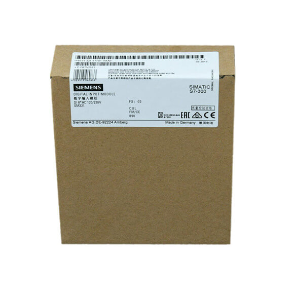
| Article number | 6ES7321-1EL00-0AA0 | 6ES7321-1FF01-0AA0 | 6ES7321-1FF10-0AA0 |
| SM321, 32DI, AC120V | SM321, 8DI, AC120/230V | SM321, 8 DI, AC/DC 120/230V, 1ch/common | |
| Load voltage L1 | |||
|
● Rated value (AC)
|
120 V | 230 V; 120/230 V AC | 230 V; 120/230 V AC; all load voltages must have the same phase. |
| Input current | |||
| from backplane bus 5 V DC, max. | 16 mA | 29 mA | 100 mA |
| Power loss | |||
| Power loss, typ. | 4 W | 4.9 W | 4.9 W |
| Digital inputs | |||
| Number of digital inputs | 32 | 8 | 8 |
| Input characteristic curve in accordance with IEC 61131, type 1 | Yes | Yes | |
| Input characteristic curve in accordance with IEC 61131, type 2 | Yes | ||
| horizontal installation | |||
|
— up to 40 °C, max.
|
32 | ||
|
— up to 60 °C, max.
|
24 | 8 | 8 |
| vertical installation | |||
|
— up to 40 °C, max.
|
32 | 8 | 8 |
| Input voltage | |||
|
● Type of input voltage
|
AC | AC | AC |
|
● Rated value (AC)
|
120 V; 47 … 63 Hz | 230 V; 120/230 V AC (47 … 63 Hz) | 120 V; 120/230 V AC (47 … 63 Hz) |
|
● for signal “0”
|
0 to 20V | 0 to 40V | 0 to 40V |
|
● for signal “1”
|
74 to 132V | 79 to 264V | 79 to 264V |
| Input current | |||
|
● for signal “1”, typ.
|
21 mA | 6.5 mA; (120 V); 11 mA (230 V) | 7.5 mA; (120 V); 17.3 mA (230 V) |
| Input delay (for rated value of input voltage) | |||
| for standard inputs | |||
|
— parameterizable
|
No | No | No |
|
— at “0” to “1”, max.
|
15 ms | 25 ms | 25 ms |
|
— at “1” to “0”, max.
|
25 ms | 25 ms | 25 ms |
| Cable length | |||
|
● shielded, max.
|
1 000 m | 1 000 m | 1 000 m |
|
● unshielded, max.
|
600 m | 600 m | 600 m |
| Encoder | |||
| Connectable encoders | |||
|
● 2-wire sensor
|
Yes | Yes | Yes |
|
— permissible quiescent current (2-wire sensor), max.
|
4 mA | 2 mA | 2 mA |
| Interrupts/diagnostics/status information | |||
| Alarms | No | No | No |
| Diagnostics function | No | No | No |
| Alarms | |||
|
● Diagnostic alarm
|
No | No | No |
|
● Hardware interrupt
|
No | No | No |
| Diagnostics indication LED | |||
|
● Group error SF (red)
|
No | No | No |
|
● Status indicator digital input (green)
|
Yes; per channel | Yes | Yes |
| Potential separation | |||
| Potential separation digital inputs | |||
|
● between the channels
|
No | No | Yes |
|
● between the channels, in groups of
|
8 | 2 | 1 |
|
● between the channels and backplane bus
|
Yes; Optocoupler | Yes; Optocoupler | Yes; Optocoupler |
| Isolation | |||
| Isolation tested with | 2 500 V DC | 4 000 V DC | 1 500 V AC |
| Connection method | |||
| required front connector | 40-pin | 20-pin | 40-pin |
| Dimensions | |||
| Width | 40 mm | 40 mm | 40 mm |
| Height | 125 mm | 125 mm | 125 mm |
| Depth | 120 mm | 120 mm | 120 mm |
| Weights | |||
| Weight, approx. | 300 g | 240 g | 240 g |